

Sensor Module
Description
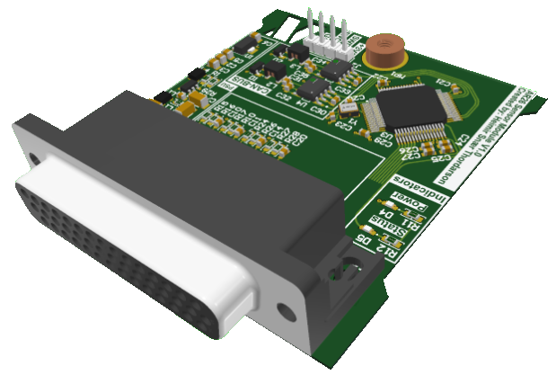
The Sensor module is designed to measure any extra analog signals rear of the firewall. For AR26, the module is designed to measure two suspension displacement sensors, two oil temperature, four water pressure, four water temperature, and one air temperature sensor. All of the measurements are then transmitted to a CAN network, which there are two of.
Wiring Diagram
In the following section, how the sensor module is connected will be covered. The connector for the sensor module is a High-Density d'sub-44 which is directly solderen onto the circuit board. The plug needed for this system is the 204517-3, which uses crimps instead of solder cups which is common for the dsub connectors
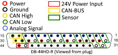
In the figure above, the pinout shows how the pins are divided. Each box shows which pins belong together for each usecase, where the red box is the power input. Yellow boxes are for each canbus network, while the green box is for each sensor used in AR26.
| Pin Number | Pin Name | Type | Pin | Pin name | Type |
|---|---|---|---|---|---|
1 | Air Temperature | Analog (0-3.3V) | 16 | GND | |
| 2 | Suspension Displacement Left | Analog (0-3.3V) | 17 | 3V3 | |
| 3 | Suspension Displacement Right | Analog (0-3.3V) | 18 | 3V3 | |
| 4 | Oil Temperature Right | Analog (0-3.3V) | 19 | 3V3 | |
| 5 | Oil Temperature Left | Analog (0-3.3V) | 20 | 3V3 | |
| 6 | Cooling Temperature 4 | Analog (0-3.3V) | 21 | GND | |
| 7 | Cooling Pressure 4 | Analog (0-5V) | 22 | 3V3 | |
| 8 | Cooling Temperature 3 | Analog (0-3.3V) | 23 | GND | |
| 9 | Cooling Pressure 3 | Analog (0-5V) | 24 | 3V3 | |
| 10 | Cooling Temperature 2 | Analog (0-3.3V) | 25 | GND | |
| 11 | Cooling Pressure 2 | Analog (0-5V) | 26 | 3V3 | |
| 12 | Cooling Temperature 1 | Analog (0-3.3V) | 27 | GND | |
| 13 | Cooling Pressure 1 | Analog (0-5V) | 28 | 3V3 | |
| 14 | CAN High 1 | CAN-BUS | 29 | CAN Low 2 | |
| 15 | CAN Low 1 | CAN-BUS | 30 | CAN Hig |
Typical Application
Design
Bill of Materials
Cost
FAQ