

Power controller
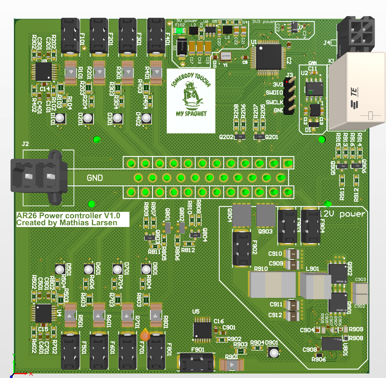
Table of contents
- AR27 Concept
Pinout
Connector pinout
| Pin | Signal | Comment | |
|---|---|---|---|
| 1 | CANH | ||
| 2 | CANL | ||
| 3 | FAN 1 PWM | ||
| 4 | FAN 2 PWM | ||
| 5 | GND | Solder blob | |
| 6 | GND | Solder blob | |
| 7 | GND | Solder blob | |
| 8 | GND | Solder blob | |
| 9 | Accumulator | ||
| 10 | Front | ||
| 11 | Power fan | ||
| 12 | Power fan | ||
| 13 | GND | ||
| 14 | GND | ||
| 15 | GND | ||
| 16 | GND | ||
| 17 | GND | ||
| 18 | GND | ||
| 19 | GND | ||
| 20 | GND | ||
| 21 | GND | ||
| 22 | GND | ||
| 23 | GND | ||
| 24 | 12V | ||
| 25 | 12V | ||
| 26 | 12V power pump 1 | ||
| 27 | 12V power pump 2 | ||
| 28 | GND | Solder blob | |
| 29 | GND | Solder blob | |
| 30 | GND | Solder blob | |
| 31 | Buzzer | Is brake light in wiring harness | |
| 32 | Brake light | Is buzzer in wiring harness | |
| 33 | 24V | Reserve | |
| 34 | 24V | Reserve | |
| 35 | 24V | Sensor card |
Microcontroller pinout
The power controller uses a microcontroller to control the pumps, fans, buzzer and brake light. It also handles current monitoring and the LED indicators. The microcontroller used in this system is the STM32G431CBT6.
| Physical pin | Electrical pin | Description |
|---|---|---|
| 1 | VBAT | Backup battery supply, used if an RTC is needed (connected to +3V3 in this design) |
| 5 | OSC_IN | Clock input (8 MHz oscillator) |
| 7 | NRST | Active-low reset, can be connected to a button (connected to +3V3) |
| 8 | PA0 | Analog signal: Current 6, supply 24 V reserve |
| 9 | PA1 | Analog signal: Current 7, supply 24 V reserve |
| 10 | PA2 | Analog signal: Current 5, supply sensor card |
| 11 | PA3 | Analog signal: Current 4, supply front |
| 12 | PA4 | Analog signal: Current 3, supply accumulator |
| 13 | PA5 | Analog signal: Current 2, supply fans |
| 14 | PA6 | Digital output: LED 9 |
| 15 | PA7 | Digital output: LED 2 |
| 16 | PB0 | Analog signal: Current 8, supply buzzer and brake light |
| 17 | PB1 | PWM: Enable fan 1 |
| 18 | PB2 | Input: V-sense |
| 19 | VSSA | Voltage source: Ground |
| 20 | VREF | Voltage reference (internal voltage reference) |
| 21 | VDDA | Voltage source: Power (+3V3) |
| 22 | PB10 | Digital output: LED 8 |
| 23 | VSS | Voltage source: Ground |
| 24 | VDD | Voltage source: Power (+3V3) |
| 25 | PB11 | Analog signal: Current 1, internal components |
| 26 | PB12 | Analog signal: Current 9, supply 12 V pumps, inverter and data logger |
| 29 | PB15 | PWM: Enable fan 2 |
| 30 | PA8 | Digital output: Enable buzzer (on the car it is the brake light) |
| 31 | PA9 | Digital output: Enable brake light (on the car it is the buzzer) |
| 32 | PA10 | Input: ASMS signal |
| 33 | PA11 | CAN bus RXD |
| 34 | PA12 | CAN bus TXD |
| 35 | VSS | Voltage source: Ground |
| 36 | VDD | Voltage source: Power (+3V3) |
| 37 | PA13 | SWDIO |
| 38 | PA14 | SWCLK |
| 40 | PB3 | Digital output: LED 3 |
| 41 | PB4 | Digital output: LED 4 |
| 42 | PB5 | Digital output: LED 5 |
| 43 | PB6 | Digital output: Enable pump 1 |
| 44 | PB7 | Digital output: Enable pump 2 |
| 45 | PB8 | Digital output: LED 6 |
| 46 | PB9 | Digital output: LED 7 |
| 47 | VSS | Voltage source: Ground |
| 48 | VDD | Voltage source: Power (+3V3) |
Distribution circuit
Green LED
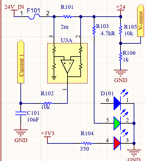
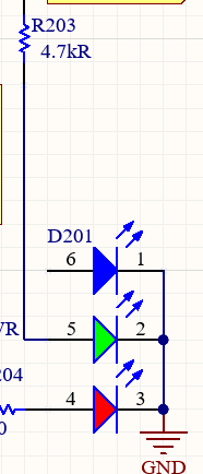
The green LED indicates whether the fuse is intact.
Current sense
Shunt resistor
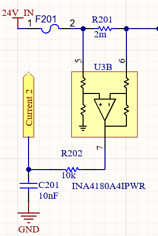
A 2 mΩ shunt resistor is placed in series with the load. The voltage drop across it is 2 mV per ampere of current (0.002 V/A).
Amplifier
The amplifier is a quad-channel current sense amplifier with a gain of 200 V/V. When the measured voltage drop passes through the amplifier, the output is therefore 0.4 V per ampere.
Filter
The filter is a low-pass filter with a cutoff frequency of 1.6 kHz.
Power amplifier
Voltage measurement
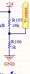
A voltage divider with a ratio of 1:11 is used, so 24 V corresponds to 2.182 V on the microcontroller pin.
12 V supply (did not work)
The buck converter overheated under load and made a whining sound.
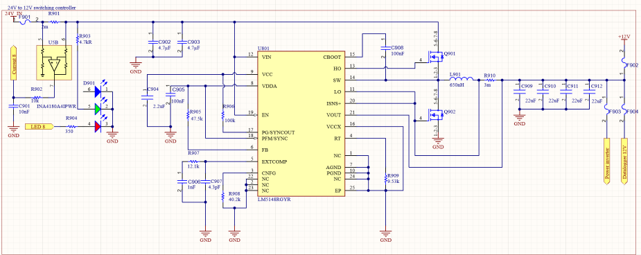
A Mateksys PM20S-2 power module was used as a quick fix to provide 12 V for the competition.
5 V, 3.3 V and CAN bus
Uses the standard Align template.
Control logic
Sourced from the microcontroller
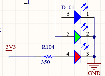
The programmable red light is part of the same RGB LED.
Current is sourced directly from the microcontroller through a 350 Ω series resistor.
High-side switching
Buzzer and brake light
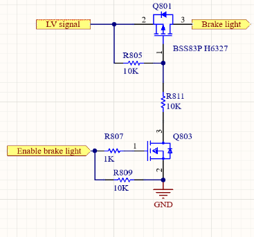
The buzzer and brake light are switched on the high side using an N-channel MOSFET (BSS123NH6327XTSA1) that drives a P-channel MOSFET (BSS83PH6327XTSA1).
Pump
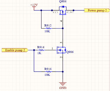
The N-channel MOSFET (BSS123NH6327XTSA1) is the same as for the buzzer and brake light, but the P-channel MOSFET (BSC084P03NS3GATMA1) has a much higher current rating.
Known issues
- The 12 V supply did not work.
- The current measurement has not been tested.
Features to add
- Add MOSFETs to cut power if the LV battery voltage is too low, to save power.
- Add power distribution for the autonomous system.
BOM (bill of materials)
| Part Number | Description | Ref Des | Qty | Manufacturer | MPN |
|---|---|---|---|---|---|
| CC0603KRX5R6BB475 | Chip Capacitor, 4.7µF +/-20%, 10V, 0603 | C1 | 1 | Yageo Group | CC0603KRX5R6BB475 |
| CL10B104KA8NNNC | MLCC, 0.1 uF, 25V, ±10%, X7R, 0603 | C2, C3, C4, C8, C9, C10, C14, C15, C16 | 9 | Samsung Electro-Mechanics | CL10B104KA8NNNC |
| CL10B105KA8NFNC | MLCC, 1uF, 25V, 10%, X7R, 0603 | C5, C7 | 2 | Samsung Electro-Mechanics | CL10B105KA8NFNC |
| CL10B103KB8NNNC | MLCC, 10nF, 50V, +125C, X7R, ±10%, 0603 | C6, C101, C201, C301, C401, C501, C601, C701, C801, C901 | 10 | Samsung Electro-Mechanics | CL10B103KB8NNNC |
| 885012206020 | MLCC, General Purpose, 0603, 100nF, 10V | C11 | 1 | Wurth Elektronik | 885012206020 |
| 885012006051 | MLCC, General Purpose, 0603, 10pF, 50V | C12, C13 | 2 | Wurth Elektronik | 885012006051 |
| 885012208124 | MLCC, General Purpose, 1206, 2.2µF, 100V | C17, C19 | 2 | Wurth Elektronik | 885012208124 |
| 885012108022 | MLCC, General Purpose, 1206, 10µF, 50V | C18 | 1 | Wurth Elektronik | 885012108022 |
| 885012206071R | MLCC, General Purpose, 0603, 100nF, 25V | C20 | 1 | Wurth Elektronik | 885012206071R |
| 885012107014 | MLCC, General Purpose, 0805, 10µF, 16V | C21, C22 | 2 | Wurth Elektronik | 885012107014 |
| MBASU105SB5104KFNA01 | MLCC, 50V, 10%, X5R, 0.1uF, 0402 | C23, C24 | 2 | TAIYO YUDEN | MBASU105SB5104KFNA01 |
| GRM32ER71H475KA88L | MLCC, 1210, 4.7uF, 50V, ±10%, X7R | C902, C903 | 2 | Murata | GRM32ER71H475KA88L |
| GRM188R71A225KE15D | MLCC, 0603, 2.2uF, X7R, 10V | C904 | 1 | Murata | GRM188R71A225KE15D |
| CC0402KRX7R6BB104 | Chip Capacitor, 100nF +/-20%, 10V, 0402 | C905, C908 | 2 | Yageo Group | CC0402KRX7R6BB104 |
| GRM1555C1H102JA01J | MLCC, 0402, 1nF, 50V, ±5%, C0G | C906 | 1 | Murata | GRM1555C1H102JA01J |
| GRM1555C1H4R3CA01D | MLCC, 0402, 4.3pF, 50V, C0G, ±0.25pF | C907 | 1 | Murata | GRM1555C1H4R3CA01D |
| GRM32ER61E226KE15L | MLCC, 1210, 22uF, 25V, X5R | C909, C910, C911, C912 | 4 | Murata | GRM32ER61E226KE15L |
| 824094024 | WE-TVS TVS Diode, SOT23-3L, 2 Channel, 24V, 38pF | D1 | 1 | Wurth Elektronik | 824094024 |
| 824500261 | WE-TVSP SMT Power TVS Diode, DO-214AC, 400W, 26VDC | D2 | 1 | Wurth Elektronik | 824500261 |
| 150282M167310 | WL-SFTD Full-color Top LED, 2828, R/G/B, 70° | D101, D201, D301, D402, D501, D601, D701, D801, D901 | 9 | Wurth Elektronik | 150282M167310 |
| 01550900DR | Fuseholder - Acs Nano | F101, F201, F301, F401, F501, F601, F701, F801, F901, F902, F903, F904 | 12 | Littelfuse | 01550900DR |
| 0466.125NR | Electric Fuse, Very Fast Blow, 0.125A, 125VAC/VDC, 1206 | F102 | 1 | Littelfuse | 0466.125NR |
| 776231-1 | Conn Shrouded Header, HDR 35 POS, 4mm, Thru-Hole | J1 | 1 | TE Connectivity | 776231-1 |
| 76829-0002 | Mega-Fit Straight Male Header, 2x2, 5.7mm Pitch | J2 | 1 | Molex | 76829-0002 |
| (4 pin header) | 2.54mm pitch 1x4 vertical header | J3 | 1 | Generic | |
| 44914-0401 | Conn Header Vert 4POS 3mm | J4 | 1 | Molex | 44914-0401 |
| 1461247-3 | Relay, Gen Purpose, SPST, 8A, 24V | K1 | 1 | TE Connectivity | OJ-SH-124LMH,000 |
| 784234510 | WE-CNSA Common Mode Line Filter, 1210, 7850Ω, 200mA | L1 | 1 | Wurth Elektronik | 784234510 |
| 74438323100 | WE-MAPI SMT Power Inductor, 2510, 10µH, 0.9A, 733mΩ | L2, L3 | 2 | Wurth Elektronik | 74438323100 |
| XAL7070-651MEB | General Purpose Inductor, 0.65uH, 20%, 3028 | L901 | 1 | Coilcraft | XAL7070-651MEB |
| BSS123NH6327XTSA1 | MOSFET N-CH 100V 0.19A SOT-23 | Q201, Q202, Q803, Q804, Q905, Q906 | 6 | Infineon | BSS123NH6327XTSA1 |
| BSS83PH6327XTSA1 | SIPMOS Small-Signal Transistor, -0.33A, -60V, SOT-23 | Q801, Q802 | 2 | Infineon | BSS83PH6327XTSA1 |
| IAUCN04S7L028ATMA1 | Mosfet, N-ch, 40V, 100A | Q901, Q902 | 2 | Infineon | IAUCN04S7L028ATMA1 |
| BSC084P03NS3GATMA1 | P-Channel OptiMOS P3, -30V VDS, -78.6A ID, PG-TDSON-8-1 | Q903, Q904 | 2 | Infineon | BSC084P03NS3GATMA1 |
| (( TBD )) | Generic Resistor, 350Ω, 0603 | R104, R204, R304, R404, R504, R606, R704, R804, R904 | 9 | (( TBD )) | |
| (( TBD )) | Generic Resistor, 1KΩ, 0603 | R205, R206, R807, R808, R913, R914 | 6 | (( TBD )) | |
| (( TBD )) | Generic Resistor, 10KΩ, 0603 | R1, R207, R208, R805, R806, R809, R810, R811, R812, R911, R912, R915, R916 | 13 | (( TBD )) | |
| (( TBD )) | Generic Resistor, 1.6KΩ, 0603 | R2 | 1 | (( TBD )) | |
| (( TBD )) | Generic Resistor, 2.2Ω, 0603 | R3 | 1 | (( TBD )) | |
| (( TBD )) | Generic Resistor, 27KΩ, 0603 | R4 | 1 | (( TBD )) | |
| (( TBD )) | Generic Resistor, 5.1KΩ, 0603 | R5 | 1 | (( TBD )) | |
| WSLF25122L000FEA | Res Metal Strip 2512, 0.002Ω, 1%, 5W | R101, R201, R301, R401, R501, R601, R701, R801, R901 | 9 | Vishay | WSLF25122L000FEA |
| CR0603-FX-1002ELF | SMD Resistor, 10kΩ, ±1%, 100mW, 0603 | R102, R105, R202, R302, R402, R502, R602, R702, R802, R902 | 10 | Bourns | CR0603-FX-1002ELF |
| CR0805-JW-472ELF | SMD Resistor, 4.7kΩ, ±5%, 125mW, 0805 | R103, R203, R303, R403, R503, R603, R703, R803, R903 | 9 | Bourns | CR0805-JW-472ELF |
| CR0603-FX-1001ELF | RES SMD 1K Ohm, 1%, 1/10W, 0603 | R106 | 1 | Bourns | CR0603-FX-1001ELF |
| CRCW060347K5FKEA | Res Thick Film 0603, 47.5KΩ, 1%, 1/10W | R905 | 1 | Vishay | CRCW060347K5FKEA |
| RC0603FR-13100KL | Chip Resistor, 100KΩ, ±1%, 0.1W, 0603 | R906 | 1 | Yageo Group | RC0603FR-13100KL |
| AC0402FR-0712K1L | Res Thick Film 0402, 12.1KΩ, 1%, 1/16W | R907 | 1 | Yageo Group | AC0402FR-0712K1L |
| CRCW060340K2FKEA | Res Thick Film 0603, 40.2KΩ, 1%, 1/10W | R908 | 1 | Vishay | CRCW060340K2FKEA |
| CRCW06039K53FKEA | Res Thick Film 0603, 9.53KΩ, 1%, 1/10W | R909 | 1 | Vishay | CRCW06039K53FKEA |
| WSR33L000FEA | Res Metal Strip 4527, 0.003Ω, 1%, 3W | R910 | 1 | Vishay | WSR33L000FEA |
| STM32G431CBT6 | MCU 32-bit ARM Cortex M4, 128KB Flash, 48-Pin LQFP | U1 | 1 | STMicroelectronics | STM32G431CBT6 |
| NCV7344D13R2G | CAN FD Transceiver, ISO 11898-2, 5Mbps, SOIC-8 | U2 | 1 | onsemi | NCV7344D13R2G |
| INA4180A4IPWR | 26V Quad Channel Current Sense Amplifier, 14-TSSOP | U3, U4, U5 | 3 | Texas Instruments | INA4180A4IPWR |
| AP64060WU-7 | DC-DC Synchronous Step Down, 4.5-40V to 0.8-26V, 0.6A, TSOT-26 | U6 | 1 | Diodes Inc. | AP64060WU-7 |
| AP2112K-3.3TRG1 | Fixed Positive LDO, 3.3V, 0.4V Dropout, PDSO5 | U7 | 1 | Diodes Inc. | AP2112K-3.3TRG1 |
| LM5148RGYR | 3.5-80V Current Mode Synchronous Buck Controller, 24-VQFN | U801 | 1 | Texas Instruments | LM5148RGYR |
| ASE-8.000MHz-E-T | Crystal Oscillator, 8MHz, 3.3V, 15pF, 4-Pin SMD | Y1 | 1 | Abracon | ASE-8.000MHZ-E-T |
AR27 Concept
This section describes the concept for AR27.
Changes
- Circuits
- More dedicated supply circuits
- Keep the same current rating
- Adjust the signal LED resistor on the PCB
- Digital signals
- Adjust the signal LED resistor on the PCB
- 12 V supply
- Three separate 12 V supplies:
- Pump 1
- Pump 2
- Inverter / other 12 V loads
- Three separate 12 V supplies:
- Autonomous
- Supplied by ASMS
- Potentially control ASSI
- ASMS state detection
Supply table
Standard supply table
| Voltage | Shared supply | Qty | |
|---|---|---|---|
| IPC | 24V | Standalone | 1 |
| Pumps | 12V | Standalone | 2 |
| Fans | 24V | Standalone | |
| HV box | 24V | Standalone | |
| Energy meter | 12V | Inverter, energy meter | |
| Inverter | 12V | Inverter, energy meter | |
| Accumulator | 24V | Standalone | |
| Brake light | 24V | Buzzer, brake light | |
| Buzzer | 24V | Buzzer, brake light | |
| Sensor module (rear) | 24V | Sensor modules, telemetry | |
| Sensor module (front) | 24V | Sensor modules, telemetry | |
| Tire temperature | 12V | Telemetry, tire temperature | |
| Telemetry | 12V | Telemetry, tire temperature | |
| Telemetry | 24V | Sensor modules, telemetry | |
| Dashboard | 24V | Standalone | |
| SDC | 24V | Standalone | |
| SDC monitor | 24V | Dashboard, telemetry, SDC monitor | |
| Internal circuitry | 24V | Standalone |
Autonomous supply table
| Qty | Current | |
|---|---|---|
| Steering motor | 1 | ? |
| ASB/ESB | ? | |
| ASSI | 2 | ? |
| RES | 1 | ? |
Relevant rules
| Rule number | Rule |
|---|---|